The kiosk case
Print and build the kiosk's wall case
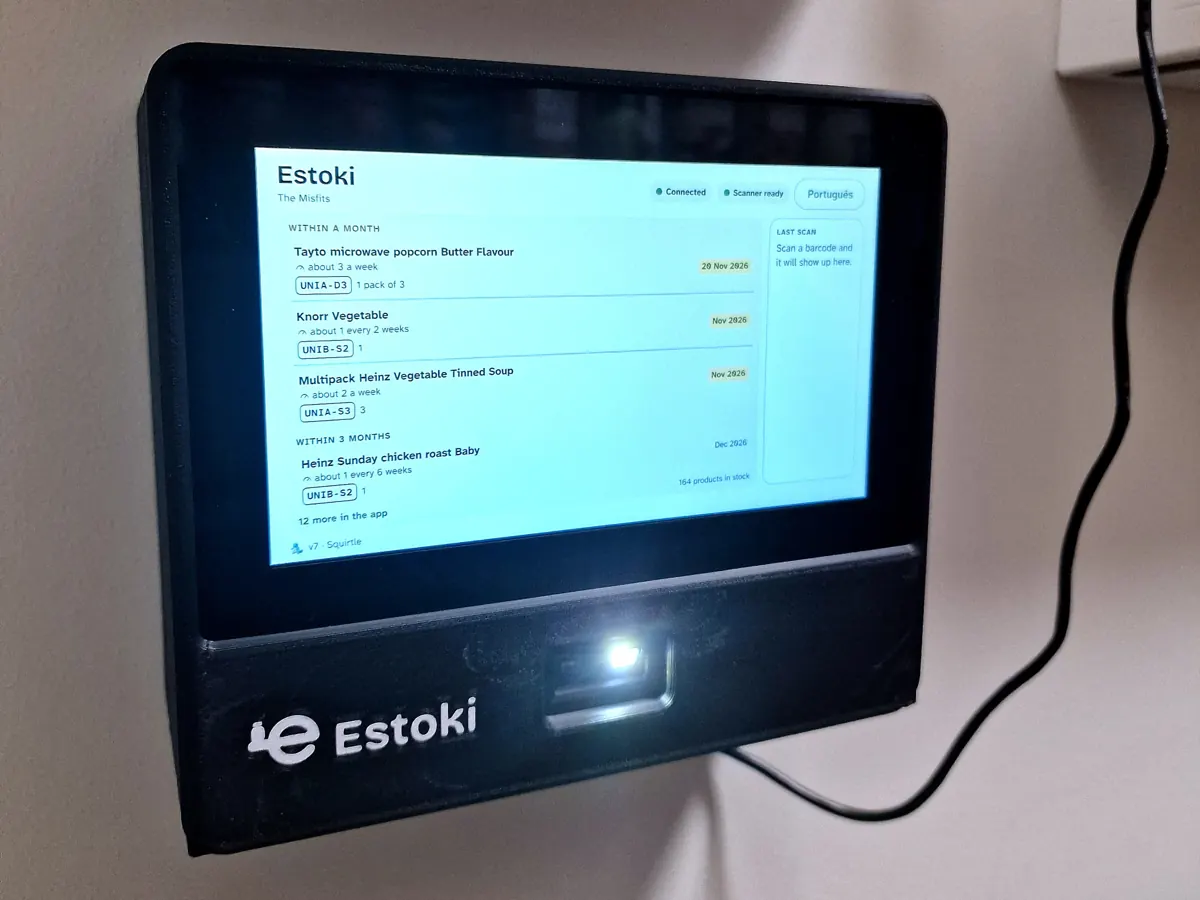
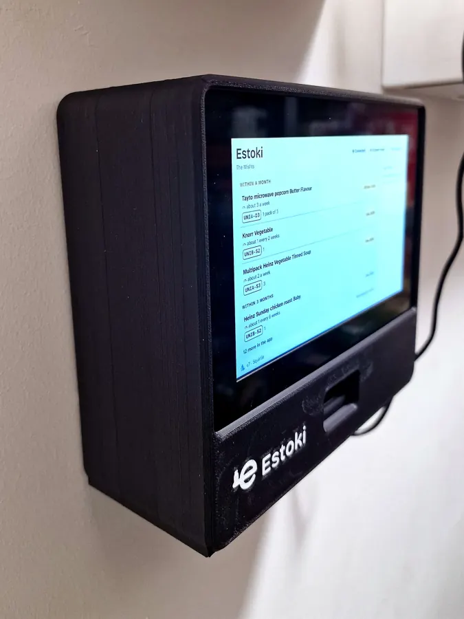
A 3D-printed case that holds a Raspberry Pi 5, the 7-inch Touch Display 2 and a barcode scanner, flat on the wall by your shelves. You hold a pack up to the window under the screen and the scanner reads it. The print files are free; this page is what to buy, how to print it and how to put it together.
The files
The print files are on Printables and MakerWorld as Raspberry Pi 5 Wall Kiosk with Barcode Scanner: every part as an STL, already lying the way it prints, and Bambu Studio projects with every part on its plates.
There are two versions of one part, the scanner nose: one for a scanner board with its brass standoffs on, as it comes, and one for a board whose standoffs have come off.
The licence
Creative Commons Attribution-NonCommercial 4.0: print it, change it and share your changes, naming Estoki, but don't sell it.
The Estoki name and mark in the face are Estoki's. Print them on your own case, but don't sell cases or anything else carrying them.
What to buy
These are the parts the case is drawn around. The links go to the makers' own pages: buy from any shop you like. None of the links on this page earn us anything.
| Part | Notes |
|---|---|
| Raspberry Pi 5, and a microSD card of 16 GB or more | The first kiosk runs on the 4 GB one. |
| Raspberry Pi Touch Display 2, 7-inch | It comes with the ribbon cable and the power lead the steps use. |
| Waveshare Barcode Scanner Module | The scanner nose is shaped for this module. It reads retail barcodes, QR codes and the GS1 codes that carry a best-before date. |
| Waveshare PoE HAT (F) | The steps are written for it: it brings the heatsink, a fan and the brass standoffs that hold the Pi to the display. With it, one Ethernet cable from a PoE+ switch or injector carries both power and network. |
| Power: the Raspberry Pi 27W USB-C power supply, or Ethernet from a PoE+ switch or injector | One or the other, never both at once: the two supplies fight. The case's underside says so too. |
| Right-angle micro-USB to USB-A cable, about 30 cm | Scanner to Pi. The plug must turn down: they're often sold as an up-and-down pair, and you want the down one. A straight plug doesn't fit behind the scanner. |
| Slim or flat Ethernet cable | For PoE: the plug has 45 mm of room inside the case. |
| M2.5 screws | One assortment of pan or button head screws from 4 to 12 mm, and four of 25 mm. Each screw cuts its own thread in the plastic. Sizes and counts are below. |
| For the wall: 3M Command Large picture-hanging strips (4 pairs), or 4 screws and wall plugs | Strips where you can't drill: four pairs hold up to 7.2 kg. |
| Two screwdrivers | A small Phillips, and a long thin one (shaft at most 5.5 mm wide and at least 65 mm long) to reach down the back cover's posts. |
Which screw goes where
All M2.5. Turn each until it's snug and stop: it cuts its own thread, and more force strips it.
| Length | How many | Where |
|---|---|---|
| 4 mm | 4 | The display to the back cover's posts |
| 6 mm | 4, or 8 | The scanner nose to the shell (4); a scanner board without standoffs to the nose (4 more) |
| 8 mm | 5 | The cleat to the back cover (3); the back cover to the top wall (2) |
| 12 mm | 7 | The chin lid to the shell (6); the lock into the wall plate (1) |
| 25 mm | 4 | The PoE HAT and the Pi to the display's posts |
Printing it
Every part prints without supports on a bed of 250 × 210 mm or more, in about 400 g of filament. The STLs already lie the way they print, so turn off auto-orient when you import them.
| Material | PETG for the case that stays on the wall: the Pi and the HAT run warm, and PLA softens at about 55 °C. PLA is fine for a first fit. |
|---|---|
| Plate | Textured PEI: the face prints against it and comes out an even matte. |
| Layers | 0.20 mm; 4 walls; 5 top and bottom layers |
| Infill | 15 %, gyroid |
| Brim | None; add 5 mm on the shell if its corners lift |
| Logo | In a second colour, open front_shell_with_logo.3mf: the logo is a second part on filament 2. In one colour, it's a 0.6 mm recess a paint pen fills well. |
Print in this order
- The wall plate and the cleat. They show how your printer handles the 0.3 mm sliding fit: the cleat should drop onto the plate and lift off without force.
- The fit test frame, about an hour: the face's first 8 mm. Check the display's glass drops into its pocket.
- The shell, the longest print.
- The back cover, the chin lid and the scanner nose.
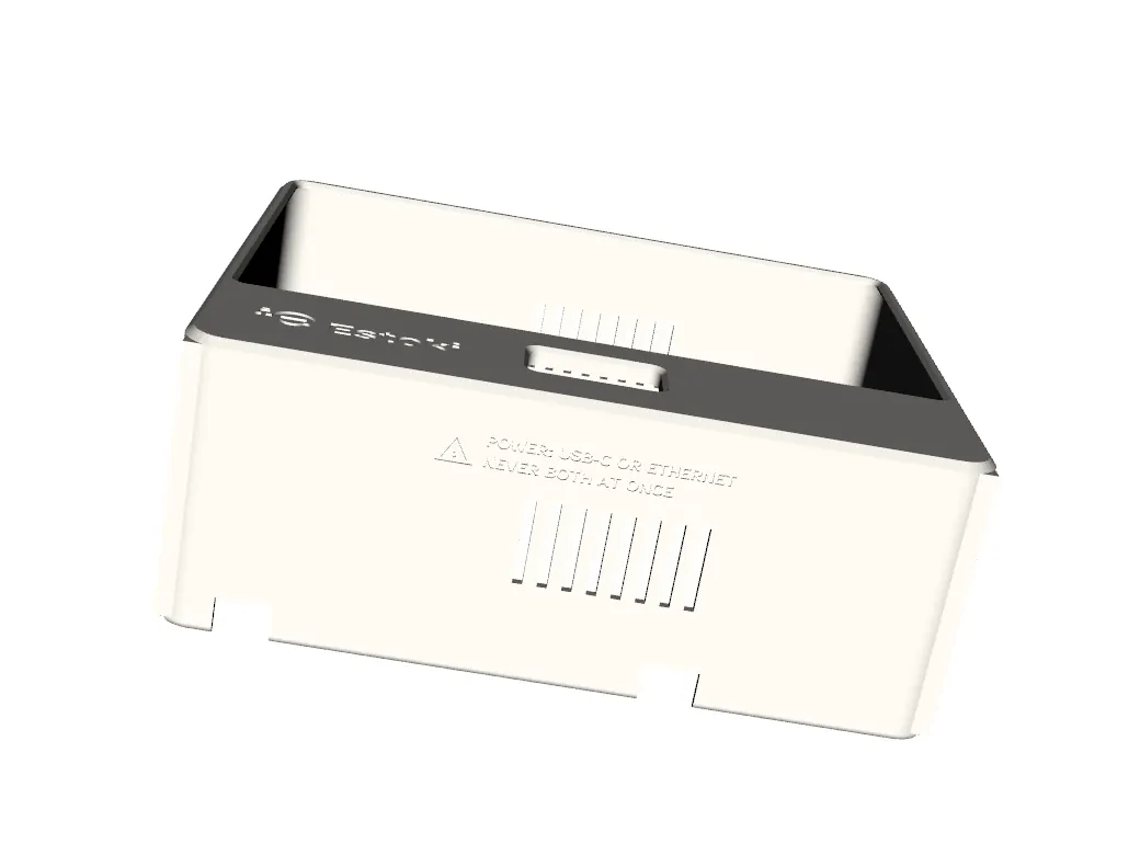
The underside, with the cable notches and the warning: USB-C or Ethernet, never both.
Putting it together
Work on a soft cloth: the display spends most of it face down.
-
The Pi onto the display
Lay the display face down, its long edges left and right of you, with the end where the glass overhangs the metal back by about 6.5 mm on your right. The edge nearest you is the bottom of the unit. Then, in this order:
- Put the microSD card in the Pi while it's loose: the slot is underneath, at the short edge opposite the USB ports. How to write the card.
- Plug the ribbon cable's wide end into the display and its narrow end into the Pi's CAM/DISP 1 socket. Do it now: the socket ends up under the HAT.
- Set the Pi on the display's four posts with its USB and Ethernet ports to your right and its USB-C towards you. Both ways round fit the posts; only this one leaves room for the plugs. Let the ribbon curve round the Pi's edge and lie flat on top.
- Fit the heatsink that comes with the HAT: its thermal pads on the chips, its two spring pins clicked into the holes beside the processor.
- Stand the four brass standoffs on the Pi's corner holes and press the HAT onto the Pi's pins. Tuck the ribbon and the HAT's fan wires clear of the standoffs first: a screw driven over a wire cuts it. Fix the stack with 4 × 25 mm screws down through the HAT, the standoffs and the Pi into the display's posts.
- The display's power lead ends in a 3-hole plug, red in hole 1 and black in hole 3. Push it onto the first three pins of the HAT's pass-through header, outer row, at the end away from the USB ports: red on pin 2 (5 V), the empty hole on pin 4, black on pin 6 (ground).
-
The scanner into its nose
Plug the right-angle cable into the module first, its plug turning down.
- A board with its standoffs (as it comes): leave the four brass standoffs on the board's underside and take their four small screws out. Slide the module into the nose, scan engine first and standoffs on the rails, until the engine touches the wall under the window. It goes in firmly: small ribs on the side walls grip the board's edges. If it won't go, shave the ribs a little with a craft knife. Put the module's own screws back down through the board and the standoffs. The front pair sit under the nose's roof: drop them in and drive them through the two holes in it with the thin screwdriver.
- A board whose standoffs came off goes in the other nose: the board sits on pads, held by 4 × 6 mm screws down through its holes, the front pair again through the roof.
A zip tie through the nose's two slots is optional.
-
The nose into the shell
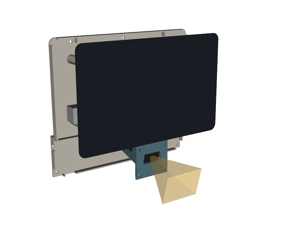
Lay the shell face down and screw the nose into the chin from inside with 4 × 6 mm screws. Look from the front: the lens should sit in the middle of the window, with no edge of the board showing.
-
The cleat onto the back cover
Square edge up, from inside, with 3 × 8 mm screws.
-
The display into the shell
Glass first, towards the lip at the front. Check there's no gap along the top.
-
The cables
The scanner's cable into one of the Pi's black USB ports. Then the power or the Ethernet cable, out through its notch at the bottom rear: USB-C or Ethernet, never both. A cable that comes out of the wall behind the unit goes through the notch in the wall plate's lower edge and the one in the chin lid's rim instead.
-
The back cover
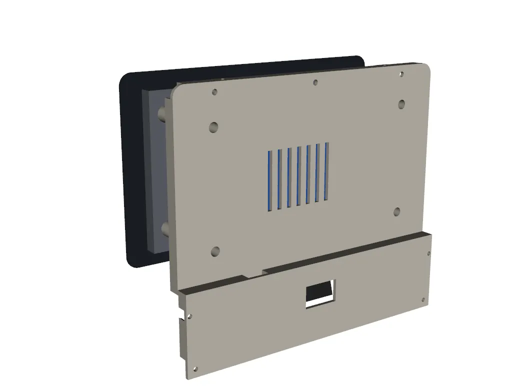
Lower it in so its four posts land on the display's case holes. Put a 4 mm screw down each post with the long screwdriver and tighten until the display stops moving. Then two 8 mm screws through the top wall.
-
The chin lid
Its rim goes behind the back cover's lower edge, with the scanner's plug in its tall window. Four 12 mm screws from behind at its corners, then two more in the counterbores along its top edge, which pull the rim and the cover together.
-
Power on and scan
Plug in the power or the Ethernet cable. A new card's first start takes a few minutes and restarts once; then link the kiosk to your household from the app. Hold a pack 5 to 20 cm from the window: the scanner lights up and reads it.
-
On the wall
The wall plate goes up with four screws through its countersunk holes, or a pair of Command strips on each outline on its back. For strips, clean the wall with isopropyl alcohol, press each strip for 30 seconds, and wait an hour before hanging the unit.
Hang the unit: hold it about 9 mm above where it will hang, so the plate's lower edge just touches the chin lid's rim inside the recess. Press it flat to the wall and lower it: its cleat drops behind the plate's. Then one 12 mm screw down through the hole in the top, near the right corner, into the plate, so it can't be lifted off by accident.
Then set it up
The kiosk app is free for every Estoki household. Writing the card and linking the kiosk to your household are on the kiosk page.
A part that doesn't fit, or a step that isn't clear? Support. What the kiosk's account can see and do is in the privacy policy.